Categoría

How to Select the Right Feeder Box for Your Busbar Trunking System?

Wrong feeder box choices cause costly rework. Learn how to select feeder box for busbar trunking system — covering current ratings, entry positions, and pole configurations.
Jun 24th,2026 11 Puntos de vista

Engineers who have commissioned a busbar trunking installation know the pattern well: the busbar run itself gets specified carefully — current rating, conductor material, run length, mounting arrangement — and then, somewhere close to the procurement deadline, someone asks about the feeder box. At that point, the decisions that should have been made at the drawing stage get compressed into a rushed conversation, and the result is often a mismatch in current rating, the wrong entry position, or a pole configuration that does not align with the busbar conductors. Rework on site is expensive. Delays to energization are more expensive still.

This guide exists to prevent that. At ZHERUTONG, we manufacture and supply busbar trunking feeder boxes across a current range from 160 A through 4000 A, and the selection questions we field most often from electrical engineers and project procurement officers informed every section below. We will work through rated current, conductor material, IP rating, entry position, pole configuration, cable entry direction, and short-circuit withstand — in the sequence that actually matters for making a correct specification.

What Does a Feeder Box Actually Do?

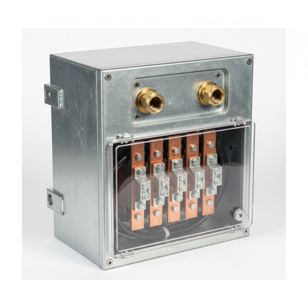
A feeder box — sometimes called a feed unit or feed-in box — is the interface component that connects the incoming power cable from a transformer, switchboard, or generator directly into the busbar trunking run, controlling how electrical energy enters the system at a defined point.

This distinction matters more than it might appear. A feeder box is the power entry point into the busbar run — it introduces current, it does not branch it. Tap-off units do the opposite: they draw current out of the run to supply downstream loads. Termination end caps seal the far terminus of the run and carry no current at all. Confusing these three components at the procurement stage is one of the most common sources of specification errors we see when engineers come to us mid-project.

In a typical system layout, the feeder box sits at one or both ends of the busbar run, or at a mid-span position when the run is long enough to warrant center feeding. The complete assembly — including the feeder box — falls under IEC 61439-6, which governs the performance requirements for busbar trunking systems and their feed units. ZHERUTONG feeder boxes are designed as matched components to our busbar trunking series, not universal aftermarket fittings, which means the mechanical interface, conductor alignment, and IP continuity are engineered as a system from the outset.

Which Selection Parameters Should Engineers Prioritize First?

Rated current capacity is the non-negotiable starting point — the feeder box must match or exceed the busbar trunking system's rated current, and every other parameter is evaluated within that constraint.

How Does Rated Current Affect Your Choice?

The feeder box rated current must align with the busbar trunking system's ampere rating — mismatching even by one standard tier, such as specifying a 400 A box on a 630 A run, creates a thermal bottleneck at the entry point that can compromise the entire installation.

Common current tiers for LV busbar trunking feeder boxes run from 160 A up through 250 A, 400 A, 630 A, 800 A, 1000 A, 1250 A, 1600 A, 2000 A, 2500 A, 3200 A, and 4000 A. The important discipline here is to verify the rating against the transformer or upstream overcurrent protective device output, not simply against the busbar run nameplate. In one data center project where ZHERUTONG supplied 2000 A feeder boxes, the customer's initial specification was based on nameplate transformer output without accounting for a 45°C plant ambient temperature. We flagged the derating requirement during drawing review — at 45°C, the effective current-carrying capacity of the feeder box needed to be recalculated downward, and the correct solution was to move up one current tier rather than accept a marginal installation. Derating for ambient temperatures above 40°C is a requirement that gets missed frequently in tropical climates and hot industrial environments.

Does Conductor Material Change the Decision?

Yes — the feeder box conductor material must match the busbar trunking system's conductor material to avoid galvanic corrosion at the joint interface and to maintain consistent thermal performance along the run.

Copper conductors offer higher electrical conductivity and allow a more compact cross-section for a given current rating, which makes copper feeder boxes the preferred choice in high-density installations or where physical space is constrained. Aluminum conductors are lighter and carry a lower material cost, which makes them common in industrial plants and infrastructure projects where weight and budget are primary drivers. The key technical fact to keep in mind: aluminum conductivity is approximately 61% that of copper, which is why an aluminum feeder box rated for the same current as a copper equivalent will have a noticeably larger physical footprint. Where the incoming cable conductor material differs from the busbar system conductor — for example, an aluminum cable connecting to a copper busbar run — bimetallic transition plates at the joint interface are the correct solution. Skipping this step and making a direct aluminum-to-copper bolted joint introduces galvanic corrosion risk that degrades contact resistance over time and can lead to overheating at the connection point.

What IP Rating Is Right for Your Environment?

For standard indoor dry environments, IP54 is the accepted minimum per IEC 60529; outdoor, wet-area, or dusty industrial installations typically require IP65 or higher, and in submersible or wash-down scenarios, IP68 becomes the specification baseline.

Environment Type

Recommended IP Rating

Typical Application Example

Indoor commercial, dry

IP54

Office towers, shopping centers

Industrial plant, covered

IP65

Manufacturing facilities, warehouses

Outdoor substation, exposed

IP65–IP66

Outdoor switchyards, rooftop plant rooms

Food processing, wash-down

IP66

Meat processing, beverage plants

Water treatment, submersible

IP68

Pump stations, underground vaults

One practical caution: avoid over-specifying IP rating as a default safety margin. A higher IP rating requires more robust cable entry gland arrangements, adds cost to the feeder box, and can complicate the gland plate configuration for the incoming cable. ZHERUTONG offers feeder boxes from IP54 through IP68 across our product range — the correct choice is determined by the actual site environment classification, not by a conservative default.

Is an End Feed Box or Center Feed Box Better for Your Project?

The choice between an end feed box and a center feed box is determined by where the power source is physically located relative to the busbar run — end feeding suits runs where the power entry point is at one terminus, while center feeding is the right solution when the transformer or switchboard is positioned mid-run, which halves the effective current-carrying length and reduces voltage drop significantly.

When Is an End Feed Box the Standard Choice?

An end feed box is the default for most straightforward installations where the power source — transformer secondary terminals or main switchboard — is located at one end of the busbar trunking run.

The mechanical arrangement is straightforward: the incoming cable enters from one side and connects to the busbar conductors at the terminal end of the run. End feed boxes are suitable for shorter runs — typically under 30 to 40 meters for medium current ratings — where the voltage drop accumulated across the full run length remains within the project's acceptable limits. High-rise riser applications are a classic example: the main switchroom sits at ground floor level, and the busbar trunking runs vertically upward through the building, with the feeder box at the base of the riser.

When Does a Center Feed Box Become the Better Option?

A center feed box becomes the technically correct choice when the busbar run exceeds the length where end feeding would cause unacceptable voltage drop at the far terminus, or when the power source is structurally located at the midpoint of the distribution path.

By feeding at the center of the run, current flows in both directions from the entry point. Each half of the run carries only half the total current, which reduces resistive losses and keeps voltage drop at the far ends of both halves within acceptable limits. This arrangement is particularly relevant for long horizontal runs in industrial plants, warehouses, and airport terminals. We have seen cases where a warehouse installation defaulted to end feeding on a 60-meter horizontal run at 800 A — the voltage drop at the far end of the run was outside the permissible limit, and the project required retrofitting a center feed box at the midpoint after commissioning. That is an avoidable cost when the run length and source location are known at design stage.

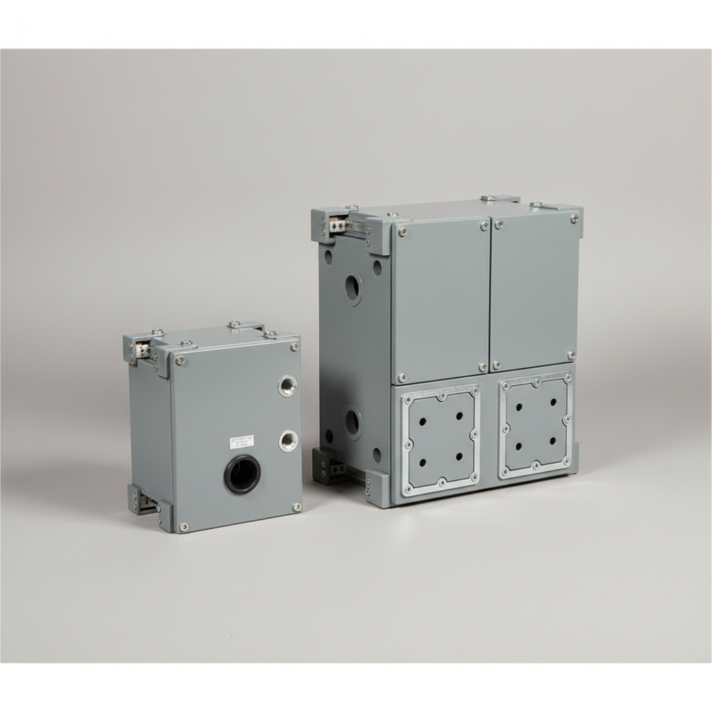
Center feed boxes are physically larger than end feed equivalents and require more installation clearance — procurement teams need to account for this in shaft or ceiling void planning. Note also the two sub-variants: center feed module left (BL) and center feed module right (BR). The designation refers to which side of the box the busbar run exits, not the physical orientation of the cable entry, and the correct variant depends on the site layout.

Parameter

End Feed Box

Center Feed Box

Power entry position

At run terminus

At run midpoint

Typical run length suitability

Shorter runs

Longer runs

Voltage drop profile

Accumulates toward far end

Balanced across both halves

Installation complexity

Lower

Moderate

Physical size

Compact

Larger footprint

What Other Specifications Are Easy to Overlook?

Beyond current rating and entry position, the specifications that most commonly cause late-stage changes are pole configuration, cable entry direction, and short-circuit withstand rating.

Does Pole Configuration Matter?

Yes — the feeder box must match the conductor configuration of the busbar trunking system, whether that is 3P, 3P+N, or 3P+N+PE, because specifying the wrong pole count means the box cannot physically connect to the run.

The most common configuration for industrial and commercial LV systems is 3P+N+PE, sometimes designated T2 in manufacturer coding — five conductors in total. Data centers, semiconductor facilities, and medical environments often require a variant with a dedicated clean ground or functional earth, which is a separate conductor from the protective earth. This is not a detail to confirm at delivery — it needs to be verified against the busbar trunking system drawing before the order is placed. The pole count is a fixed physical dimension of the busbar run and cannot be adjusted on site.

How Does Cable Entry Direction Affect Installation?

Feeder boxes are available with top, bottom, or side cable entry, and selecting the wrong entry direction relative to the cable routing path can force bends that violate minimum cable bend radius requirements or make the installation physically impossible without rework.

Top entry suits vertical cable drops from overhead trays or conduit. Bottom entry suits floor-level or underfloor cable routing. Side entry is useful in tight plant rooms where the cable arrives from a horizontal tray at the same elevation as the busbar. This is one of the customization points ZHERUTONG discusses early with OEM clients and project engineers, because it is a straightforward question to resolve at the RFQ stage and a genuinely difficult problem to fix on site after the feeder box has been mounted.

Is Short-Circuit Withstand Rating a Selection Variable?

Absolutely — the feeder box must be rated to withstand the prospective short-circuit current at the point of installation, which is determined by the upstream transformer impedance and the fault loop impedance of the system.

Typical Icw values for industrial LV systems are 50 kA / 1 s and 80 kA / 1 s. IEC 61439-6 requires that the short-circuit withstand capability of the complete busbar trunking system — including its feed units — be verified by test or calculation. Under-specifying Icw is a safety risk; over-specifying adds cost without benefit. The correct value comes from the project's short-circuit study, and it should be confirmed before finalizing the feeder box specification.

How Do You Avoid the Most Common Specification Mistakes?

The most avoidable mistakes in feeder box selection come not from ignorance of the parameters, but from treating the feeder box as a last-minute accessory rather than a first-principles design decision made alongside the busbar trunking run specification.

Based on the projects we have reviewed at ZHERUTONG — including cases where engineers came to us after running into difficulties — five patterns appear repeatedly. First: selecting the feeder box current rating from the busbar nameplate without checking actual design load current and ambient derating factors. Second: specifying copper conductor feeder boxes on an aluminum busbar trunking system without a bimetallic transition, which leads to corrosion and hot joints over time. Third: defaulting to an end feed box on long runs because it is more familiar, then discovering voltage drop issues at the far end after commissioning — the warehouse retrofit scenario described earlier is a real pattern, not a hypothetical. Fourth: ignoring cable entry direction until installation day, which is a five-minute conversation at the ordering stage and a significant cost to resolve on site. Fifth: not confirming pole configuration against the busbar system drawing — a 3P+N box cannot interface with a 3P+N+PE busbar run, and this is a fixed constraint with no field workaround.

None of these mistakes require specialized knowledge to avoid. They require asking the right questions at the right stage of the project. Sharing your single-line diagram and site environment details with ZHERUTONG at the RFQ stage eliminates most of these risks before they become problems.

---

Selecting a feeder box for a busbar trunking system is a multi-variable decision, but each variable is answerable if you approach it in the right sequence: rated current first, then entry type, conductor material, IP rating, pole configuration, cable entry direction, and short-circuit withstand. Work through them in order and the specification writes itself.

If you are at the planning or procurement stage of a busbar trunking installation, send your project drawings and specifications to rtdq@rtbusway.com — include your busbar trunking current rating, installation environment, and run length, and our engineering team will recommend the right busbar trunking feeder box configuration for your project.

---

Frequently Asked Questions

Q1: What is the difference between a feeder box and a tap-off unit in a busbar trunking system?

A feeder box introduces power into the busbar trunking run from an external source such as a transformer or switchboard. A tap-off unit draws power out of the run to supply a downstream load. They serve opposite functions and are not interchangeable. Confusing the two at the procurement stage is one of the most common ordering errors we encounter.

Q2: Can I use an aluminum feeder box with a copper busbar trunking system?

It is not recommended without a bimetallic transition interface at the joint. Direct aluminum-to-copper contact in a bolted connection creates galvanic corrosion risk over time, which progressively degrades contact resistance and can lead to overheating at the feeder box connection point. Bimetallic transition plates are the correct solution when the cable conductor material differs from the busbar conductor material.

Q3: How do I determine whether my project needs an end feed box or a center feed box?

Check where your power source is located relative to the busbar run and calculate the expected voltage drop across the full run length at the design load current. If the source is at one end and the run is relatively short, end feeding is the standard choice. For longer runs, or where the power source is structurally located at the midpoint of the distribution path, center feeding is the technically correct solution. The busbar trunking end feed box vs center feed box difference comes down to source location and run length — both are answerable from your single-line diagram.

Q4: What IP rating should I specify for an outdoor substation installation?

Outdoor installations generally require a minimum of IP65 to protect against water jets and dust ingress. In environments with direct rain exposure or regular wash-down procedures, IP66 is more appropriate. Confirm the site's environmental classification before specifying — the busbar trunking end feed box vs center feed box decision and the IP rating decision should both be made with reference to the actual installation conditions, not conservative defaults.

Q5: Does ZHERUTONG supply feeder boxes with custom cable entry configurations?

Yes. ZHERUTONG can configure cable entry direction — top, bottom, or side — along with gland plate sizing and pole configuration to match project-specific requirements. Send your drawings and specifications to rtdq@rtbusway.com for a customization review.


CONTACT US

If you have any queries, get in touch today! Don't hesitate. We try to take the extra step for our customer satisfaction.
First Name *
Company Name *
Email *
Last Name
Country
Message *
Leave a message
First Name *
Company Name *
Email *
Last Name
Country
Message *