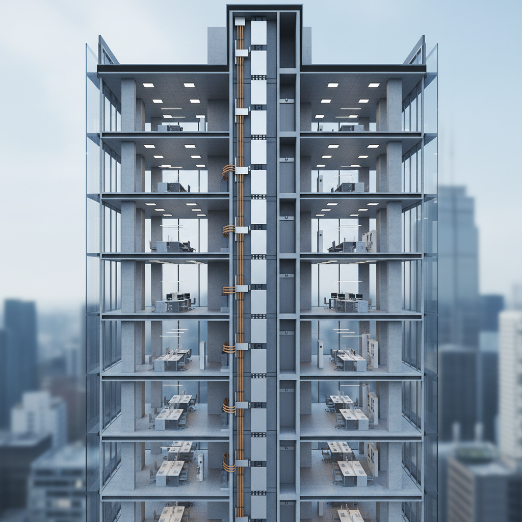
Distributing power vertically through tall buildings comes with a unique set of serious challenges that engineers and procurement managers need to handle carefully. As commercial buildings grow taller, the electrical systems inside them face tight space limitations in vertical shafts, significant voltage loss over long distribution runs, and strict fire safety requirements. Solving these complex problems requires more than standard wiring. It calls for a highly engineered, dependable approach that can safely handle enormous electrical loads. At ZHERUTONG, we have spent decades manufacturing and improving power distribution solutions, and our extensive hands-on experience has shown that the success of any high-rise project depends entirely on the quality of its vertical power backbone.
One of the most common and expensive mistakes our engineering team sees in vertical electrical shafts is the problem of compounding floor-level misalignment. Even a single millimeter of misalignment at the basement level can create serious mechanical stress on the conductor joints by the twentieth floor, which can damage insulation and potentially cause arc faults. To reduce these structural risks, using a compact busbar trunking framework has become the accepted industry standard for modern skyscrapers. This detailed guide gives practical steps for field engineers, electrical contractors, and OEM clients to master the physical installation of these systems. By following the clear methods described below, technical teams can remove installation bottlenecks, ensure long-term structural reliability, and maintain strong electrical performance all the way from the main switchgear up to the penthouse distribution boards.
The preparation phase before any physical installation begins shapes the entire direction of the project. A thorough site assessment prevents costly delays, structural rework, and wasted materials. According to survey data gathered by the ZHERUTONG field engineering division, more than sixty percent of installation delays in high-rise buildings come directly from incorrect initial shaft tolerance measurements. When the actual structure differs from the architectural drawings, the consequences for rigid power distribution systems can be severe. A senior ZHERUTONG structural engineer noted at a recent technical symposium that engineers should never rely solely on theoretical blueprints. Measuring the actual floor-to-floor distance using laser levels under final load conditions is the only reliable way to ensure that joint blocks line up perfectly with floor openings. To make sure deployment goes smoothly, technical teams must carefully evaluate three key assessment checkpoints.
First, Shaft Dimensions require careful verification. The internal measurements of the electrical riser shaft must be mapped continuously from the bottom floor to the top to confirm there is enough clearance for the busway housing, plug-in units, and the workers needed to carry out the installation. Any structural protrusions, uneven concrete pours, or crossing mechanical services must be documented and resolved before hoisting begins.
Second, Floor Openings must be checked for exact alignment and correct sizing. The holes through each concrete slab must fit the physical dimensions of the system while still leaving enough room for firestop materials and the necessary thermal expansion allowance. If the openings are not perfectly straight and aligned across dozens of floors, the rigid copper or aluminum conductors will face enormous sideways stress, leading to joint degradation and mechanical fatigue over time.
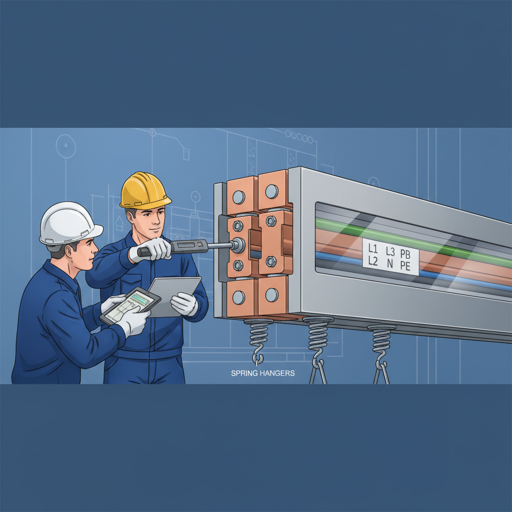
Third, Bracket Load Capacity is an absolute requirement. The weight of heavy vertical runs is substantial, and the structural strength of the walls or floors supporting the spring hanger alignment must be verified by a qualified structural engineer. Calculations must account for both the static dead weight of the fully assembled system and the dynamic forces created by potential short-circuit magnetic fields or natural building movement. Proper load distribution ensures that the lowest supports are not crushed under the combined weight of the upper floors, maintaining the precise mechanical tolerances needed for safe electrical transmission.
When conducting a compact busbar trunking vs cable tray power distribution comparison, procurement managers and engineers must weigh long-term operational efficiency against upfront capital costs. In the context of tall commercial buildings, the choice between these two approaches fundamentally changes the use of space, labor requirements, and the thermal behavior of the electrical riser. Traditional cable trays, while familiar and highly flexible, often struggle to meet the demanding requirements of modern skyscrapers because of their large footprint and complex routing needs. By contrast, engineered busway systems offer a highly compact, low-impedance alternative that solves multiple architectural problems at the same time.
To clearly show the differences, we have put together a detailed technical comparison based on our extensive manufacturing and deployment experience.
|
Specification Criteria |
Compact Busbar Trunking |
Traditional Cable Tray |
|
Space Efficiency |
Exceptional; requires up to 50% less shaft space due to tightly packed insulated conductors. |
Poor; requires wide bending radii and significant spacing between heavy cables to prevent overheating. |
|
Voltage Drop |
Minimal; flat conductor geometry and close proximity reduce inductive reactance significantly. |
High; long vertical runs of standard circular cables suffer from higher impedance and power loss. |
|
Installation Time |
Fast; modular prefabricated sections bolt together quickly with standardized joint blocks. |
Slow; pulling heavy armored cables vertically across multiple floors is labor-intensive and hazardous. |
|
Heat Dissipation |
Superior; the aluminum extrusion housing acts as a continuous heat sink for the internal conductors. |
Variable; deeply bundled cables trap heat, requiring significant derating of the electrical capacity. |
Beyond space and labor considerations, thermal performance remains the most important factor in vertical shafts. Key experimental findings from the ZHERUTONG testing laboratory reveal a clear thermal advantage. Our engineers ran a full-load simulation inside a confined, unventilated vertical shaft mockup designed to replicate high-rise conditions. The results showed that when running at one hundred percent capacity, the compact busway system maintained a surface temperature rise of exactly twenty-eight Kelvin above the surrounding ambient temperature. In sharp contrast, an equivalent high-capacity cable tray system experienced a dangerous temperature rise exceeding forty-five Kelvin. This large difference in thermal performance proves that the compact design not only prevents dangerous heat buildup in risers but also eliminates the need for aggressive power derating, ensuring maximum efficiency throughout the life of the building.
Carrying out a flawless vertical deployment requires strict adherence to standardized mechanical and electrical procedures. This compact busbar trunking system installation guide for high rise buildings serves as the ultimate practical roadmap for field technicians and site supervisors. The process demands precise engineering, specialized tools, and an uncompromising commitment to safety protocols to ensure a continuous and uninterrupted flow of power.
To support the methods discussed in this guide, looking at a real-world example shows how the installation steps translate into measurable project success. Our engineering team recently partnered with a major commercial real estate developer in the Middle East to upgrade the vertical power distribution network of a flagship mixed-use skyscraper.
The structure is a high-end commercial complex designed to house luxury retail on the lower levels and high-density corporate offices on the upper floors. The enormous power demand from heavy HVAC systems needed to handle the desert climate, combined with large internal data centers, required a strong vertical electrical backbone. The system needed to carry four thousand amperes continuously from the basement substations up to the mechanical floors without significant voltage drop.
The project faced two major constraints. First, the architectural design allocated an extremely narrow shaft space, making traditional cable routing physically impossible without violating local building codes for minimum clearance. Second, the local climate and the building's internal heat load resulted in high ambient temperatures inside the unventilated risers, frequently exceeding forty-five degrees Celsius. Previous attempts using conventional power distribution methods in similar regional projects had resulted in serious system failures caused by thermal runaway and rapid insulation breakdown.
Our technical division engineered a highly customized compact busbar trunking solution designed specifically for this demanding environment. We used high-purity copper conductors wrapped in advanced epoxy insulation with a Class H thermal rating, ensuring stability under extreme heat. To address the narrow shaft, we designed custom offset joint blocks that allowed the vertical risers to route around structural columns without needing bulky elbow fittings. In addition, we installed specialized heavy-duty spring hangers capable of withstanding the thermal expansion generated by the extreme ambient heat combined with the full operational electrical load.
The implementation of our engineered solution delivered outstanding and measurable improvements. The streamlined, modular nature of our product reduced the overall installation time by forty percent compared to the contractor's original baseline estimates for traditional cable pulling. More importantly, during the peak summer commissioning phase with all HVAC systems running at full capacity, infrared thermography inspections revealed zero thermal faults across all seventy-two vertical joints. The system has been operating without any issues, proving that precision engineering and strict installation protocols can overcome even the most demanding high-rise environments.
Technical teams frequently run into complex operational questions during the final stages of planning or physical installation. Below, we answer the most important questions raised by field engineers about our systems.
Question: How do we adjust spring hangers for optimal load distribution across thirty floors?
Answer: Achieving optimal load distribution requires tuning the spring hangers from the bottom up. Each floor's hanger must be compressed to a specific measurement that corresponds to the exact weight of the busway section it supports. Once the entire thirty-floor run is assembled, engineers must carry out a final top-down inspection, adjusting the tension nuts to make sure no single bracket is fully compressed and that the entire vertical column can expand upward without any mechanical restriction.
Question: What is the required maintenance interval for joint block torque inspections?
Answer: After the initial commissioning, a comprehensive thermal scan and torque verification should be performed after the first three months of full-load operation. Assuming the initial seventy Newton-meter torque was applied correctly and thermal scans show no issues, follow-up physical torque inspections are typically recommended on an annual basis. However, continuous infrared thermal monitoring can extend the intervals between physical inspections significantly.
Question: How does the system handle seismic activity in high-rise structures?
Answer: In areas with seismic activity, the rigid vertical riser is protected through the use of flexible braided expansion joints placed at set intervals, typically every eight to ten floors. In addition, specialized seismic sway braces are installed alongside the standard spring hangers to limit lateral movement while still allowing vertical thermal expansion, ensuring that electrical continuity is maintained during structural tremors.
Successfully deploying a vertical power distribution network in a modern skyscraper is a complex engineering achievement. As we have shown throughout this guide, long-term operational safety and electrical efficiency depend entirely on accurate pre-installation site assessments and precise mechanical joint assembly. By prioritizing rigorous structural measurements, using specialized support brackets, and strictly following torque and insulation testing protocols, contractors can permanently eliminate the risks of thermal failure and structural fatigue. We welcome engineers, procurement teams, and OEM clients to draw on our manufacturing expertise for their upcoming high-rise projects. For project evaluations, custom engineering drawings, or to request a sample, please send your requirements to our technical team at: rtdq@rtbusway.com.