Categoría

Rising Main vs Busbar Trunking System Selection Guide for High Rise Buildings

Neither system wins every project. This rising main vs busbar trunking system selection guide for high rise buildings helps MEP engineers make the right call.
Jun 18th,2026 24 Puntos de vista

Picture a site engineer crouched in a ceiling plenum with 180 mm of vertical clearance, working on a power upgrade in a 30-year-old commercial tower where every structural beam, HVAC duct, and sprinkler line is already competing for the same narrow corridor. Traditional cable trays won't fit — not with the bending radius that heavy power cables demand. Conventional busbar runs need elbow room that simply isn't there. This is the exact scenario we at ZHERUTONG designed our compact busbar trunking line to solve, not just in theory, but with a repeatable, field-tested installation process. This guide walks through everything from pre-installation space assessment to joint torquing and final commissioning, with the granular detail that generic product pages consistently skip.

Why Does Space Geometry Determine Everything Before Installation Starts?

Before a single bracket goes up, the physical geometry of your installation corridor — ceiling height, wall offsets, column positions, and thermal clearance gaps — dictates which compact busbar trunking configuration is viable and which will fail inspection or overheat in service.

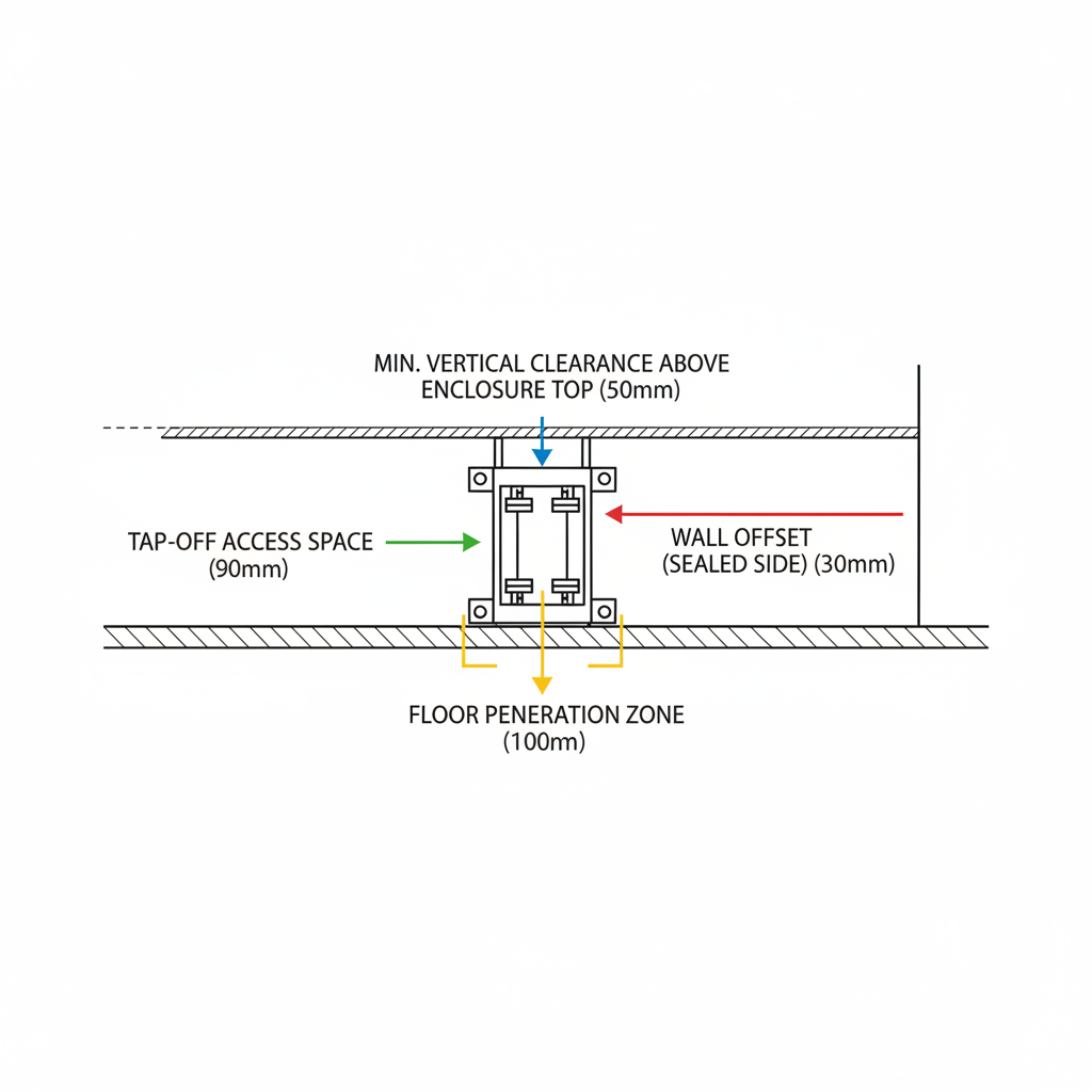
The most skipped step on tight-space projects is the spatial audit, and it is also the most consequential. Sandwich-type compact busbars rely on the aluminum housing itself as a primary cooling surface. Block that surface with a structural beam sitting 80 mm above the enclosure top, and you change the derating curve in ways that won't show up until the system is under full load in summer. Our working rule: allow at least 150 mm of clear air above the enclosure top for heat dissipation, at least 50 mm on tap-off access sides, and at least 20 mm on sealed sides. For floor penetration zones, measure slab thickness plus fire barrier sleeve depth before specifying feed-through units — these two dimensions together determine the feed-through unit length, and getting it wrong means a custom modification on site.

The routing path sketch matters more than the straight run. Every direction change — a horizontal-to-vertical transition, a 90° flat bend around a column, an offset elbow to clear a duct — adds physical length to the order and creates a jointing point that needs torque access space around it. At ZHERUTONG, we ask every customer to submit a hand-drawn or CAD routing sketch before we finalize the bill of materials. In one commercial renovation project, that sketch caught a column conflict at the third direction change that would have required a custom offset elbow to resolve. Without the sketch, the crew would have discovered the problem overhead, mid-installation, costing at least two weeks of on-site modification time.

Load calculation must also account for the confined environment. Compact busbar trunking cross-sections are optimized for current density, but when ambient temperature inside a ceiling void exceeds 40°C at peak load season — not just the room temperature below — derating applies. Engineers should measure or estimate void temperature under realistic conditions, not in an empty building on a mild day.

Two pre-installation mistakes we see repeatedly: ordering standard 3-meter straight sections without accounting for the cumulative length consumed by elbows and expansion joints, and ignoring the relationship between access panel positions and tap-off unit locations. Both are correctable on paper. Neither is correctable easily once the run is hung.

How Do You Select the Right Fittings for Confined Routing?

Fitting selection in tight-space installations is not about catalog browsing — it is about matching each direction change and connection point to the exact angular and spatial constraints of your route, because a mismatched elbow or an oversized joint cover creates a bottleneck that no amount of on-site improvisation fixes cleanly.

Elbow type is the first decision point. Flat elbows turn in the horizontal plane and are the correct choice when routing within a low-headroom ceiling void where vertical space is the binding constraint. Edge elbows turn in the vertical plane and are used when the route needs to transition between ceiling and riser. For non-standard angles — anything that isn't a clean 30°, 45°, 60°, or 90° — adjustable-angle elbows eliminate the need for a custom section. They add approximately 40–60 mm to the jointing zone compared to fixed elbows, so that extra length must be budgeted in the routing sketch. At ZHERUTONG, our adjustable elbows include a locking mechanism that holds the set angle during installation, which matters significantly when one person is aligning the fitting overhead with limited visibility.

Expansion joints become mandatory on any run exceeding approximately 20 meters in a temperature-variable environment. Thermal elongation in a constrained shaft generates axial force that joints are not designed to absorb. The expansion joint must be positioned where there is enough longitudinal clearance for it to slide — typically 25–30 mm of travel range — which means the position must be planned before ordering, not decided on site.

Tap-off unit placement logic is frequently treated as an afterthought and shouldn't be. Each tap-off box requires clear space in front of its door panel for operation and future circuit changes. In corridors where ceiling access is possible from only one side, every tap-off position must face that accessible side. This sounds obvious in a planning meeting. It is frequently overlooked when the busbar is installed before ceiling finishes are confirmed.

On conductor material: copper conductors deliver higher current density in a smaller cross-section, which is directly relevant when enclosure width is the binding constraint. A compact copper busbar trunking system rated at 1000A typically fits within 100–120 mm enclosure width. An equivalent cable tray bundle carrying the same current requires 300 mm or more of tray width, plus additional spacing between cables, plus bending radius allowances at every turn. Aluminum conductors are lighter — important for long overhead runs with limited hanger points — but require a larger cross-section for equivalent ampacity, which increases enclosure width.

What Are the Step-by-Step Installation Procedures That Actually Work in Tight Spaces?

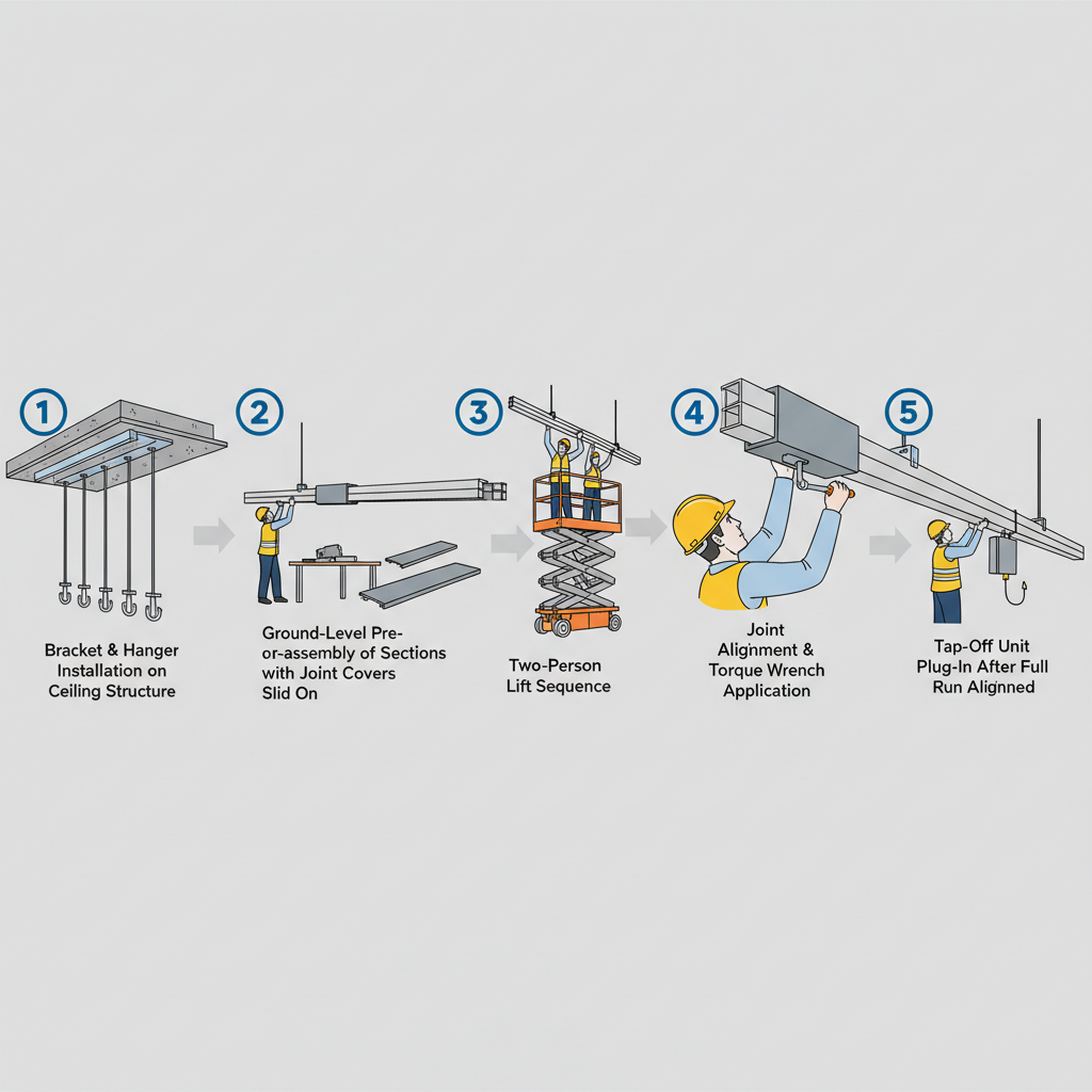
A successful compact busbar trunking installation in a confined space follows a non-negotiable sequence — support system first, sections assembled on the ground where possible, lifted and joined in controlled stages — because attempting to joint overhead in a 200 mm plenum without a pre-planned sequence turns a half-day job into a two-day problem.

How Do You Set Up the Support System First?

The hanger and bracket system must be fully installed and load-tested before any busbar section is lifted, because adjusting support positions after the run is in place is nearly impossible in tight spaces.

Hanger spacing for horizontal compact busbar trunking runs is typically 1.5–2.5 meters, depending on current rating and section weight. Vertical riser runs use 2–3 meter spacing, with each section independently supported — joints are not structural connections and must never be treated as load-bearing points. In tight ceiling voids, spring-loaded or adjustable-height hangers allow fine-tuning after the busbar is resting in position, which is far easier than repositioning a fixed bracket. Verify that every hanger attachment point — concrete anchor, beam clamp, or threaded rod — is rated for combined busbar weight plus the dynamic load from thermal expansion cycling.

How Do You Sequence the Section Assembly Overhead?

Start from the feed-in end and work toward the far terminus, assembling no more than two or three sections before making each joint, so that alignment errors do not compound across the full run.

The most important pre-lift task is sliding joint covers onto each section before it goes up. In a 180 mm ceiling void, it is physically impossible to add a joint cover after two sections are already joined overhead. This single preparation step is where sites that follow the pre-assembly sequence save 35–40% of total installation time compared to sites that skip it — a pattern we have observed consistently across confined-space projects.

Lift sequence: one person supports the free end of the section, one aligns the joint. In very tight spaces, a temporary support bracket at the joint location holds the section while bolts are torqued. Joint bolt torque must follow the manufacturer's specification — ZHERUTONG provides torque values per conductor size and joint type in the installation manual. Under-torquing is the leading cause of hot joints in service, and in a tight space where thermal imaging of joints is difficult post-installation, an under-torqued joint becomes a latent fault that is expensive to diagnose and repair. Before closing any joint cover, verify phase continuity with a continuity tester. Once the cover is on in a confined space, reopening it costs significant time.

How Do You Handle Vertical Riser Installations Differently?

Vertical riser runs in tight shafts require spring-loaded hanger assemblies and fire barrier sleeves at every floor penetration, and the weight of each section must be independently supported rather than transferred to the joint above.

Fire barrier sleeves at floor slabs must be fitted before the busbar section passes through — retrofitting them afterward is not feasible in a tight shaft. Anti-vibration pads at hanger points reduce the effect of building movement on joints over the system's service life. Phase orientation marks on each section end are especially critical in vertical runs, where sections are sometimes rotated during the lift sequence and a 180° phase reversal at a joint is easy to introduce and difficult to detect once the cover is closed.

Is Compact Busbar Trunking Actually Better Than Cable Tray in Tight Spaces?

For runs longer than 15 meters in a space-constrained corridor, compact busbar trunking consistently outperforms cable tray on three measurable dimensions — installed cross-section width, direction-change flexibility, and post-installation modification cost — though cable tray retains an advantage for highly irregular, multi-branch low-current distribution.

The number that matters on site is cross-section footprint. In a 250 mm ceiling void, the difference between a 110 mm busbar enclosure and a 350 mm cable tray bundle is not a matter of preference — it determines whether the solution fits at all. The compact busbar trunking vs cable tray space saving comparison becomes particularly stark at direction changes: cable tray requires a bending radius of 6–8 times the cable diameter for heavy power cables, and in tight spaces that radius simply does not exist. Compact busbar trunking uses factory-made elbows with fixed, predictable geometry — no bending radius penalty, no site improvisation required.

Criterion

Compact Busbar Trunking

Cable Tray + Cable

Installed width at 1000A

100–130 mm

300–400 mm + spacing

Direction change method

Factory elbow, fixed geometry

Bending radius 6–8× cable diameter

Post-installation tap-off

Plug-in unit, no rewiring

Pull new cable, disturb existing runs

IP protection (standard)

IP55

Depends on cable type and tray cover

Modification labor cost

Low

High

Cable tray remains the better choice for highly irregular branch distribution with many small loads at unpredictable positions, for very low current applications below approximately 250A where the compact busbar cost premium is not justified, and for outdoor exposed runs where weatherproof cable tray may be simpler to source locally. The compact busbar trunking vs cable tray space saving comparison is not a universal verdict — it is a decision that depends on run length, current level, and how many direction changes the route requires.

What Are the Most Common Installation Errors and How Do You Avoid Them?

The installation errors that generate the most costly rework in tight-space busbar projects are not electrical mistakes — they are mechanical sequencing errors and measurement oversights that become exponentially harder to correct once the run is enclosed or the ceiling is finished.

Ordering straight sections at nominal length without accounting for fitting depth is the most common BOM error. Each elbow, expansion joint, and feed-in box consumes length from the adjacent straight section. Subtract the jointing depth of every fitting from the straight section length at that position — ZHERUTONG includes fitting depth tables in every project BOM template precisely because this step is so frequently skipped.

Skipping torque verification on joints is the most common field error. Specify a calibrated torque wrench as mandatory site equipment, not optional. In a confined space where joints cannot be easily accessed for thermal scanning after installation, the only reliable quality check is correct torque at the time of assembly.

Installing tap-off units before the full run is aligned adds unnecessary weight and shifts the center of gravity of individual sections during the lift sequence. Install tap-off units only after the full run is hung, aligned, and all joints are torqued to specification.

Ignoring thermal expansion in short runs is more common than it should be. Engineers often assume expansion joints are only necessary for long runs. In a tight space where the busbar is constrained between two fixed structural elements, even a 10-meter run can generate significant axial force if no expansion accommodation is provided — particularly in plant rooms or risers with large temperature swings between shutdown and full-load conditions.

Finally, mismatched phase orientation at joints. In tight spaces where sections are lifted from different angles and orientations, a section can be rotated 180° accidentally before the joint is made. Mark phase orientation clearly on both ends of every section before it leaves the ground.

---

What Questions Do Engineers Ask Most About Tight-Space Busbar Installation?

What is the minimum ceiling void depth for compact busbar trunking?

The absolute minimum void depth depends on the enclosure height of the specific current rating, but as a working rule, allow at least 150 mm above the enclosure top for heat dissipation and a minimum of 50 mm below for joint bolt access. Tighter clearances are possible in some configurations, but they require a formal derating calculation and should be confirmed with the manufacturer before ordering.

Can compact busbar trunking run horizontally and vertically in the same route?

Yes — transition elbows connect horizontal and vertical segments within the same run, and ZHERUTONG manufactures these in both fixed and adjustable angles to accommodate non-standard shaft geometries. The transition point must be supported independently on both the horizontal and vertical segments.

How do you derate a compact busbar system installed in a hot ceiling void?

When ambient temperature inside the installation void exceeds 40°C, the rated current must be derated according to the manufacturer's temperature correction table — typically a 1–2% reduction per degree Celsius above the 40°C baseline, though the exact factor depends on enclosure design and conductor material. Always measure or estimate void temperature under peak load conditions, not ambient room temperature.

Is IP55 protection standard for indoor tight-space installations?

IP55 is the common standard for compact busbar trunking used in indoor commercial and industrial installations, providing adequate protection against dust ingress and water jets — sufficient for ceiling voids, risers, and plant rooms in typical building environments. Higher IP ratings are available for more demanding environments.

How long does a 30-meter confined-space installation typically take?

With a two-person crew following a pre-planned sequence — support system pre-installed, sections pre-assembled on the ground — a 30-meter straight run with three or four fittings typically takes one full working day in a tight space. Without pre-planning the sequence, the same run routinely takes two or more days.

---

The engineer standing in that ceiling plenum at the start of this guide faces a solvable problem — but only if the preparation sequence is correct. The difference between a clean, on-spec installation and a costly rework is not the product. It is the measurement discipline before ordering, the routing sketch that catches conflicts before they become field problems, and having a manufacturer who provides project-specific support rather than a generic datasheet. At ZHERUTONG, we work directly with engineers and procurement teams from routing sketch to final commissioning, supplying compact busbar trunking systems configured to the exact spatial constraints of each project.

If you have a tight-space installation coming up — a retrofit in an existing building, a riser upgrade, or a new data center corridor — send us your project drawings or a simple hand-drawn routing sketch. Our engineering team will review the spatial constraints, recommend the correct current rating and fitting configuration, and provide a project-specific BOM. You can also request a sample section to verify fit before committing to a full order.

Reach out directly: rtdq@rtbusway.com


CONTACT US

If you have any queries, get in touch today! Don't hesitate. We try to take the extra step for our customer satisfaction.
First Name *
Company Name *
Email *
Last Name
Country
Message *
Leave a message
First Name *
Company Name *
Email *
Last Name
Country
Message *